")
")
")
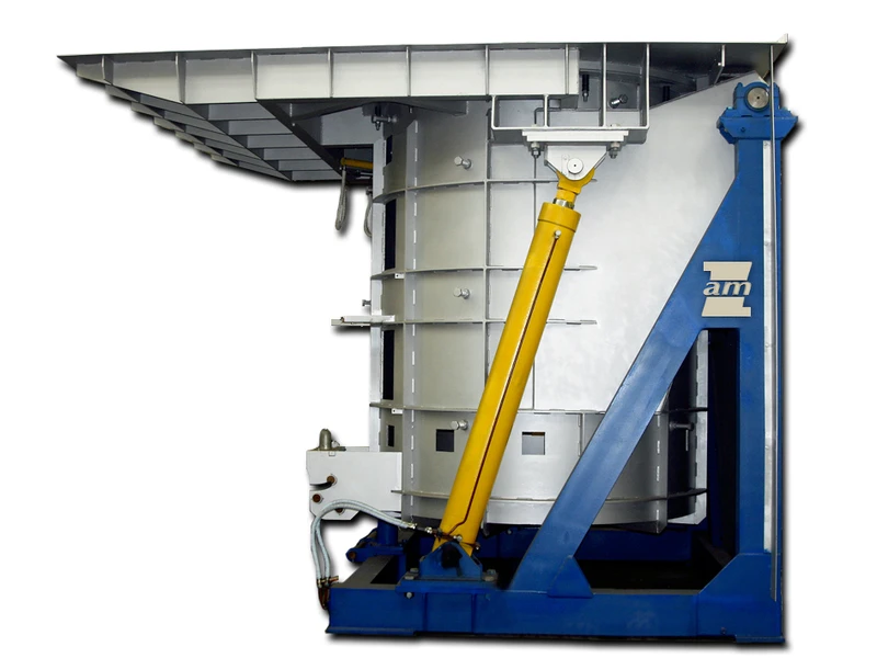
Induction furnaces
ZAM Kęty Sp. z o.o. manufactures induction furnaces of grid frequency designed for melting:
- cast-iron
- cast-steel
- aluminium
- copper
- copper alloys
These furnaces are of new generation, state-of-the-art, constructed on the basis of electronic and electric sub-assemblies of high quality and reliability. We have already been manufacturing induction furnaces for over 45 years.
The main advantage of grid-frequency furnaces is the intense stirring of metal providing homogeneity of alloys obtained. It is particularly fundamental while melting a variety of scrap metals.
Years of practice has provided us with extensive knowledge and experience what resulted in the high quality of our furnaces, particularly in their reliability, supported by the exploitation counted in tens of years.


Equipment of the furnace:
- transformer or autotransformer with tap changer
- load symmetrisation system (inductive choke and capacitor bank)
- compensation capacitor bank
- control cabinet with panel
- cooling water system
- hydraulic power system
Main sub-assemblies of induction furnace of grid frequency:
- crucible unit with inductor and magnetic shunts
- compacted crucible of ceramic material
- furnace is closed with the lid which is opened hydraulically
- hydraulic actuators are used to tilt the furnace
Advantages:
- furnaces are designed for melting, overheating and maintaining metals in the heated state, as well as manufacturing alloys and master alloys
- during melting and overheating processes, intense stirring of metal occurs, making melted charge homogeneous in terms of temperature and chemical composition
- simplicity of operation and service
Technical description
Furnace operation is controlled from the control cabinet. Power of the furnace is step-adjustable by the change of the tap of the transformer or the autotransformer. Furnace load symmetrisation and reactive power compensation is controlled in automatic mode. The furnace reaches full power when the liquid metal in the crucible reaches the level of the upper edge of the inductor coil. During the continuous operation of the furnace, the best performance is obtained when ca. 1/3 of liquid metal is left in the crucible after each melting.
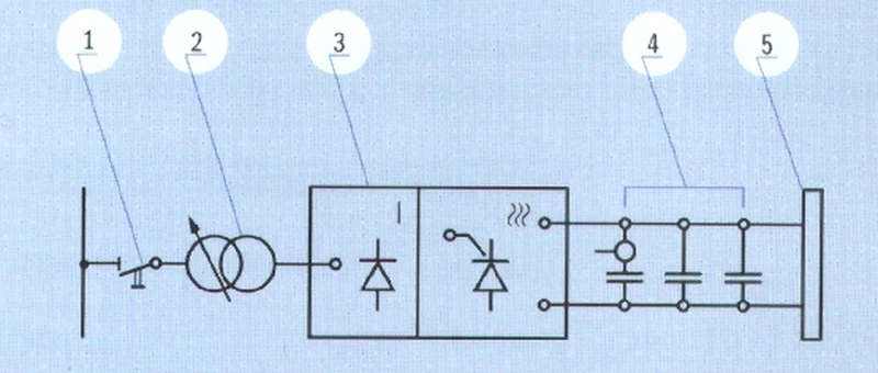
An example of the electrical diagram for the main circuit of the furnace
- Disconnector
- Short-circuit breaker
- Main contactor
- Control transformer with control – setting unit
- Resistors to limit the current connecting the furnace
- Symmetrisation system
- Compensation bank
- Inductor
Technical specification of the furnances:
We supply turnkey induction furnaces with fireproof lining, power equipment, water and hydraulic installations. After installation and technical start-up of the furnace, we offer co-participation in the technological start-up.
We offer consulting service regarding the optimal selection of the furnace.